Showing posts with label home networking. Show all posts

03 December 2008

Crazy Home Lab


Actually I found this site quite long time ago, I'm amazed by the craziness of the owner's home lab. You've probably seen this site before, since this site is quite famous.

This site is named Uber Geek, the owner of this site is Scott Morris. His resume alone is outstanding, he's a quadruple CCIE, meaning he owns all four of the CCIE tracks.
And he also wins all other networking certifications that you can dream of.

Once you see the lab he has, you'd understand what I'm saying:


I can't say anything but this lab is just crazy, not only Cisco devices but also Juniper, Sun, Dell, etc.
Some of the small ISPs in my country don't even have these kind of devices I think.

Of course with those four big racks and massive amount of devices comes a great requirements. From the heat come from the devices he made special air conditioning environment at his basement.

I know the idea to build this kind of lab is no where near possible for people that just want to pass certification exams like CCNA or even CCNP. Especially if you don't get enough income from your networking projects.
Nevertheless having a lab like this will make your future clients won't doubt about your expertise.

So I say, start building your home network lab, add in some Cisco or other devices one by one and maybe eventually you'll come close to Scott Morris' lab.

Read more!

19 November 2008

Do I Need Lightning and Surge Protection?


That was what I concerned when first building my Cisco home lab. I never concerned about this before since I only had my laptop, couple of PCs and the good old Linksys networking devices.

No matter what devices I have, I should have installed some lightning and surge protection for any electronic devices I have.

Lightning, power surges and spikes are the main enemy of electronic devices. Lightning can cause a major power surge and spike, meaning when a lightning strikes it causes a brief huge power spike which can reach a spike of 50 million volts, it's brief but deadly.

And not only surges from lightning, if you live in some old neighborhood, sometimes the electrician didn't do their work very well or perhaps the electrical installation is too old so power surges and spikes can happen any time.


Knowing this I immediately bought a power surge protector, it's a surge protector from Belkin and I use it to protect only my networking devices.

But you you never know, I only concerned about surges and spikes from electrical line, I forgot about the line that is coming from my internet cable.

About three days ago lightning stroke, I don't know where, it doesn't have to strike your home directly, it can strike your neighbor home some miles away and it can still get to you.

One lightning strike, one cable modem, one Phillips LCD TV, one computer, and one CATV splitter are dead. Warranty available for the modem and TV thank God.
Luckily my Cisco devices are okay, thanks to the power surge protector I think.

Man it was a nightmare, one big thunder and suddenly everything was down, the lights, computers, everything.
All suddenly dark, I spotted a spark somewhere, a large cracking sound, and everyone just went aaahhhhh.
Even the computers when turned on after a while, the NICs were not working for some times, luckily they do now.
Yet my laptop still mute, the speaker and some usb ports are dead.


So the moral of this story, buy some lightning and surge protectors, at least they provide protection to some degree.
You can also buy surge protectors that provide phone line protection for DSL connection or coaxial for your cable internet connection.

What about UPS, some UPS also provide lightning and surge protection, well I prefer to have both.
Plug in the surge protector first to the electric outlet and then the UPS goes to the surge protector.
And remember to buy them from a reputable vendors like APC or other brands, they cost more indeed but no doubt about the qualities.

If you don't want to buy them then the best protection when dealing with lightning strike in your home is to turn off all the devices and unplug all the power cables when it's raining heavy.

Hope this experience of mine won't happen to you.

Read more!

12 November 2008

Configuring WPA and WPA2 on Cisco Aironet


The last post I talked about configuring WEP authentication on Cisco Aironet wireless access point.
Now I want to configure WPA and WPA2 to give more strength in the wireless security.

Just for a note I put an image of padlock on the last post and now I give a picture of a vault to give the image of stronger security.
You know what I mean, padlock versus vault, oh just forget it.

Back to the topic, when first posting about WEP I said that WEP encryption is weak, you better use encryption like WPA and WPA2.

WPA gives better key management and stronger cipher encryption. For those who don't know about cipher, it's kinda algorithm for encryption and decryption, we'll be configuring the cipher when dealing with WPA and WPA2. WPA uses what is called TKIP or Temporal Key Integrity Protocol for the cipher encryption.

WPA2 is even better than WPA, it uses a stronger encryption called AES or Advanced Encryption Standard, it creates fresh sessions key so every packet sent are encrypted with different key.

One other thing to know, the WPA and WPA2 come with two flavors, the Personal and Enterprise. In enterprise mode we need to have authentication server such as RADIUS, I don't have RADIUS server currently so I'll skip to the Personal mode instead.
The personal mode of WPA and WPA2 have what is called WPA-PSK the WPA Pre-Shared Key, we have to configure the WPA-PSK on both the Access Point and the clients.

So get on to the configuration of WPA first for my SSID Guest on VLAN 40:

1240AG> enable
1240AG# configure terminal
1240AG (config)# interface dot11radio 0
1240AG (config-if)# encryption vlan 40 mode ciphers tkip
1240AG (config-if)# ssid Guest
1240AG (config-if-ssid)# vlan 40
1240AG (config-if-ssid)# authentication open
1240AG (config-if-ssid)# authentication key-management wpa
1240AG (config-if-ssid)# wpa-psk ascii your-key-here

That's it you've successfully configured WPA on Cisco Aironet Wireless Access Point. Just configure the ciphers to tkip, set the authentication to open, use the wpa key management and the great thing in WPA is that we can set ascii characters as the key instead of hexadecimal like we did on configuring WEP.

The difference of WPA with WPA2 configurations is just some small things. We have to set the ciphers to AES and the key management to WPA version 2. Let's get started to configure WPA2 for my SSID Admin on VLAN 30:

1240AG> enable
1240AG# configure terminal
1240AG (config)# interface dot11radio 0
1240AG (config-if)# encryption vlan 30 mode ciphers aes-ccm
1240AG (config-if)# ssid Admin
1240AG (config-if-ssid)# vlan 30
1240AG (config-if-ssid)# authentication open
1240AG (config-if-ssid)# authentication key-management wpa version 2
1240AG (config-if-ssid)# wpa-psk ascii your-key-here

Don't forget to check out how to set up Wireless Network and the SSID on my last posts. Cheers.

Read more!

10 November 2008

Configuring WEP Authentication on Cisco Aironet


The wireless network you installed for your LAN can mean that you are directly exposing your network to the public.

Anyone can use a wireless sniffer and view all the traffics going between the wireless access point and the clients. That's why you need to add security in your wireless LAN.

This post will talk about WEP or Wired Equivalent Privacy, the name states that your wireless network will be as safe as your wired network but not in reality.
There are many WEP decryption tools available out there. Just capture some packets using wireless sniffer and use the the decryption tool to find out the WEP key.

So we know the WEP is not secure, nevertheless I want to show how to configure WEP authentication for Cisco Aironet wireless access point.

WEP uses 40 bits encryption key (10 hexadecimal characters) or 128 bits (26 hexadecimal characters).
Don't get a false sense of security with the length of the encryption, the longer the encryption key just mean the more packets you need to capture and more time to decrypt them.

There are two types authentication for security according the IEEE 802.11 committee, the shared-key and open authentication.

In a shared-key authentication, the access point will send a challenge packet to the client and the client must encrypt the packet with with the right key (WEP key) then return it to the access point.
This method is not secure since everything sent in clear text.

The other method is open authentication, just like the name the authentication is open or you can say no authentication required.
But when open authentication used with the WEP, the WEP key will be used to encrypt all data before sending them.

I have to admit, I get a little confused when first time configuring authentication in Cisco Aironet wireless access points since no one thought me so I had to browse all the configuration examples.

It's easier to use the web interface of the access point, but I want to configure it through CLI.
To configure WEP authentication you should do this by entering the dot11radio interface:

1240AG> enable
1240AG# configure terminal
1240AG (config)# interface dot11radio 0

Create the SSID and associate it with VLAN if you haven't done it:

1240AG (config-if)# ssid Guest
1240AG (config-if-ssid)# vlan 40
1240AG (config-if-ssid)# authentication open
1240AG (config-if-ssid)# exit

Configure the WEP authentication:

1240AG (config-if)# encryption vlan 40 mode wep mandatory
1240AG (config-if)# encryption vlan 40 key 1 size 128bit 12345678901234567890123456 transmit-key

The above first command tell the Cisco Aironet to do WEP encryption on vlan 40 (SSID Guest) and set it as mandatory.
If you replace mandatory with optional, the use of WEP encryption depends on the client configuration, they can choose to encrypt the packets or not.

The second command tells the access point to use the WEP encryption key of 128 bit with the above 26 characters key. You can use whatever key you choose as long as it is hexadecimal characters (0-9 and A-F).

Don't forget to set up the access point as I did on the last post.

Read more!

08 November 2008

Configuring Cisco Aironet in Home Lab - Part 2


Now it's time to configure Cisco Aironet Wireless Access Point for Cisco home lab.

What I'm going to do first is to configure the connectivity between the Cisco Aironet 1240AG wireless access point to the Cisco 2950 switch.

Here's the closer look of the network diagram of the wireless access point and the switch:


The network will be using VLAN 5 (192.168.5.0 network) as the native VLAN and the rest of the VLANs will be used for the SSIDs.

There's an interface called BVI or Bridge-group Virtual Interface, what this interface does is bridge all of the interfaces in the access point - the wired and wireless interfaces - so you can use the interface BVI IP address to manage all of those interfaces.

In Cisco Aironet 1240AG wireless access points, you have 1 interface fast ethernet port, 1 console port, 1 dot11radio 0 for the 802.11G, and 1 dot11radio 1 for 802.11A.

In this configuration I only going to configure the dot11radio 0 for the 802.11G wireless network since I only have the antennas for the 802.11G.
You can configure both 802.11A and 802.11G if you want.

First we configure the interface BVI 1 IP address:

1240AG> enable
1240AG# configure terminal
1240AG (config)# interface bvi 1
1240AG (config-if)# ip address 192.168.5.3 255.255.255.0
1240AG (config-if)# no shutdown

Now set the native VLAN (VLAN 5) to the wireless access point, we have to configure the native VLAN on both of the fastethernet sub interface and the dot11radio 0 sub interface:

1240AG (config)# interface fastethernet 0.5
1240AG (config-if)# encapsulation dot1q 5 native
1240AG (config-if)# interface dot11radio 0.5
1240AG (config-if)# encapsulation dot1q 5 native

Next is to set up the SSID starting from SSID for admin and associate it with VLAN 30.
We need to configure the SSID on the dot11radio 0 interface first then configure the VLAN on the dot11radio 0.30 sub interface and fast ethernet 0.30 sub interface.
Also I set up the SSID for open authentication first.

1240AG (config)# interface dot11radio 0
1240AG (config-if)# ssid ADMIN
1240AG (config-if-ssid)# vlan 30
1240AG (config-if-ssid)# authentication open
1240AG (config-if-ssid)# end

1240AG (config)# interface fastethernet 0.30
1240AG (config-subif)# encapsulation dot1q 30
1240AG (config-subif)# bridge-group 30

1240AG (config-subif)# interface dot11radio 0.30
1240AG (config-subif)# encapsulation dot1q 30
1240AG (config-subif)# bridge-group 30

The bridge-group command allows you to group interfaces and bridge nonrouted traffic among the interfaces.
In this example traffic from dot11radio 0.30 sub interface to fastethernet 0.30 sub interface and vice versa.

Note: If you configure the SSID on the global configuration mode, the SSID will be both in the dot11radio 0 and 1.

Do the same with the SSID for guest and associate it with VLAN 40:

1240AG (config)# interface dot11radio 0
1240AG (config-if)# ssid GUEST
1240AG (config-if-ssid)# vlan 40
1240AG (config-if-ssid)# authentication open
1240AG (config-if-ssid)# end

1240AG (config)# interface fastethernet 0.40
1240AG (config-subif)# encapsulation dot1q 40
1240AG (config-subif)# bridge-group 40

1240AG (config-subif)# interface dot11radio 0.40
1240AG (config-subif)# encapsulation dot1q 40
1240AG (config-subif)# bridge-group 40

Next step is to configure the switch port connected to the wireless access point as a trunk port with native VLAN 5.
I already posted about how to do this on the last post.

Also if you are going to use dynamic IP address, make sure you have configured router as DHCP server that serving clients for VLAN 30 and 40.

Right now if you have no problem pinging the switch and router from the wireless access point, your access point is broadcasting SSID and giving IP address from router for any client joining the SSID.

The SSIDs are not secure since they use open authentication, next time I'll configure it with stronger authentication.

Read more!

07 November 2008

Configuring Cisco Aironet in Home Lab - Part 1


I've configured my Cisco home lab with a router that connects to cable internet and a switch with VLANs.
Now it's time to add a new device to the Cisco home lab, a Cisco Aironet 1240AG wireless access point for wireless connection.

And by the way, the image on the left is not an official logo from Cisco or anything, I just made that up.

I won't configure anything fancy this time, only give basic administration configuration and set up an open SSIDs also associate the SSIDs to VLANs.

Since I want to configure two SSIDs - one is free for all SSID with no authentication and the other one with authentication - for the wireless network, I need to configure additional VLAN on the switch.

I have already the VLAN 30 for the wireless network and want to add VLAN 40, so in total there would be 5 VLANs in my Cisco home network lab.

I made a network diagram with Cisco Aironet 1240AG wireless access point added in the picture below:

So lets start the configuration on the next post, there are some steps to complete this Cisco home lab network diagram if you haven't done so.

Starting from the wireless access point I'm going to configure the basic administration configuration such as the access point's management IP address, SSIDs and associate them to VLANs, optionally configure the authentication security options for the SSIDs, and establish trunk connection to the switch.

For the switch I'll configure VLANs and the trunk connection to the access point and the router.

Last in the router I'll configure interVLAN routing, DHCP server for each VLAN, and other configurations like I've posted before.

Read more!

05 November 2008

Wireless Home Network


At the last post I talked briefly about the wireless site survey in networking projects.

Now I want to share my view in things that I personally consider in building wireless home network.
The following points are just my considerations, most home or SOHO users just plug their wireless access points, configure them and they just work fine.

Which Standard to Use

Currently there are four common standards for wireless networking, the 802.11a, 802.11b, 802.11g, and the latest one is 802.11n. These standards use unlicensed frequencies meaning they're all free for all to use.

You can use the frequencies for your wireless networks and you can't complain if your neighbors used up all of the frequencies available and interfere with your wireless signal.
Later on this when I talk about the wireless channels in a moment.

802.11a uses the 5GHz operational frequency and has a data rate transfer of 54Mbps. This standard is not too popular anymore because it has a higher frequency meaning it has higher data rates but with shorter range.
The higher the frequency also makes it more easily absorbed by solid objects around it.

802.11b and 802.11g use 2.4GHz operational frequency. Most wireless access points support both the b and g standards since they both use the same frequency they're both interoperable.
The difference is that the 802.11b has data rate transfer of 11Mbps while the 802.11g has 54Mbps.

The latest one is 802.11n, it uses 5GHz and/or 2.4GHz frequencies and in terms of data rate and wireless range, it has biggest data rate the widest range, some vendors claim their 802.11n access points can have data rates up to 114Mbps.

I don't know the truth about that since I don't have any 802.11n devices yet.
For me I just love the sleek looking design of 802.11n wireless router from Linksys.
Cool, gotta have that someday.

Wireless Access Points Locations

Place the access points in locations that you think can reach all the clients in the network. Consider the interferences from microwave oven or cordless phones.
Also keep in mind about objects that can block, absorb or reflect the signals from the access points such as thick wall or metal surfaces.

The further you get from the access points and the more objects standing between you and the access point, the lower data rate you'd get.

Channels to Use

If one wireless access point is enough to cover your clients, check on the wireless channels that are used by access points installed near your network.
If your access point uses the same channel as your neighbor's, they will interfere the wireless signals.
If you're using more than one access points, set them to use different channels.

In 802.11b and g standards, the common channels or the clean channels that you can use are channel 1, 6, and 11. Use one for each of your access point, do not use the same channel if the signals.
What I mean by clean channels is that these channels are not overlapping each other.
The following is the graphical representation of 802.11b and g wireless channels:

The 802.11a offers more clean channels for you to choose. You can see the wireless channels that you can use for 802.11a:


More on subjects on channels you can find directly at the source at the FCC site.

SSID

Service Set Identifier or SSID is like an ID for your wireless network. I'm sure you already know this, to join wireless network you need to know the SSID or you can scan for the SSID and join it.

You can use many available wireless network sniffers to scan the SSID and the wireless channels used by the wireless networks. Some of them you can find at the list here.
Once again not every sniffer works with your wireless network card, check on it before downloading.

You can use any SSID for your wireless network, your name, company name, etc. The reason I brought this up because if you're using the upper end wireless access points like from Cisco, you can have multiple SSID broadcasted from a single wireless access point.

Maybe you need a free for all SSID for your guests, another SSID for your home users or employees, and another one just for you as the admin.

In Cisco, you can tie these SSIDs to VLANs, this can give you flexibility in deciding different security for each SSID, different access list for them, etc.

Wireless Security


Now this is the most important part of all, the wireless security or the encryption method you want to associate with your SSID.
There are some types of wireless network authentication for security from the open authentication that you can apply for guests on your WLAN to the WPA version 2.
There are also WEP that is not so secure nowadays since people can tap on your signals and decrypt them.
Best to say that WPA or WPA2 are more secure to use in your WLAN, you can also use 802.1x security.

Remember that not all hardware or wireless NIC support all authentication, most of them support the WPA authentication so it's more common to use nowadays.

I got to admit I'm too lazy to give all explanation of them here plus this post takes longer than I expected.
Smarter and more diligent people have describe about this, one of them you can find at wikipedia.

I don't want to make you bore and start on the configuration of Cisco wireless network on the next posts.

Read more!

04 November 2008

Get to Know Cisco Aironet Wireless Access Point


Ah, I just love these things the Cisco Aironet Wireless Access Points, on the left one you can see the Cisco Aironet 1240AG Access Point, one among every other Cisco Aironet series.

This is the very first Cisco device that I got, I thought that at least I can integrate it with my existing non-Cisco home network.

1240AG is not the prettiest access point that you can get, but I like the shape anyway. It reminds me of liquor bottles that I used to see in the movies.

Now why would you want to buy Cisco Aironet, it costs about ten times or more than the average home usage access points like Linksys or D-Link.

These Aironet things are great, for the 1240AG, it has one Fast Ethernet port and one console port.
It doesn't come with integrated antennas, you have to buy them. You can use the 802.11G antennas and/or 802.11A antennas. This gives you flexibility in choosing the antennas, you can even use both if you want to.
Mind you that not all countries allow the use of 802.11A standard.

The console port as usual used for configuring the Cisco Aironet Access Point through CLI. You can also use web browser to configure the Access Point, different from other Cisco devices' web interfaces, the Aironet web interface offers rich features configuration.
Other Cisco devices have not that good appearances, you definitely prefer configuring other Cisco devices through CLI.

Below is the example of the Cisco Aironet web interface:


Unlike other Cisco devices, Cisco Aironet Access Points are by default configure to accept IP address from DHCP server, if you have DHCP server in your LAN, that's great.
Just plug in a cable to connect the access point to your LAN and as soon as it receives IP address you can do configuration for it.

One tip, for the Cisco Aironet 1100 series Access Points, they have a default IP address of 10.0.0.1 that last for just 5 minutes.
So during that 5 minutes you can configure your computer NIC for an IP address of 10.0.0.2 or other, and connect a network cable from your computer NIC to the ethernet port of the access point.
Open the web browser and type in the 10.0.0.1 address, then you can do some configuration. Remember this only last for 5 minutes, after that the access point will request IP address from DHCP address indefinitely.

Now what other features the Aironet Access Points have, many features that the average home usage access points don't have.

You can configure the Access Points to be an Intrusion Detection System (IDS) to protect your network, use it for scanning your network for rogue access points that your neighbour use for stealing your bandwidth, and they also offer the powerful 802.1x to authenticate clients.

You can also set your own transmit power and data rates of the wireless radio interfaces.

Configure several SSIDs to segment your network. Each SSID can be correlated with VLAN. Provide SSID for your guests, another SSID for your home users, and a special SSID just for administration purpose.
Want another SSID? a special SSID just for handling your VoIP packets, cool.

If you have several Cisco Aironet Access Points in your disposal, set them up so your users can roam all over the place and jump from one area of access point to another without loosing connection.

Have hundreds of Aironet Access Points in a project? You don't need to configure them one by one. Upgrade or request from Cisco for Aironet with Cisco IOS Lightweight enable mode.
With Ligthweight feature and wireless LAN controller you just need to make one configuration on the wireless LAN controller and it will send the configuration to all access points in your network.
Saves you from lot of works.

So many features to tell, to try out all these features get your own Cisco Aironet Wireless Access Points now. You won't be sorry if you're a true techies, except that your wallet would be thinner a bit. sengihnampakgigi

Read more!

30 October 2008

Adding Switch to Cisco Home Lab - Part 5


Configure Router as DHCP Server for VLANs

Now this part of configuration is the most fun part of all. I just love the way that one router accepts requests from clients on different VLANs (with different subnets), and the router gives away the addresses based on what VLAN a client resides.

That's just cool, your average home usage routers can't do this kind of stuff, most of the average home usage routers can do is just give away IP addresses for one network.

At the previous post, I posted about how to make a router to be DHCP server. Now this post is similar but I'm going to make the router to give away IP addresses for clients on different networks.

The configuration is also the same, but now I'm going to make several IP DHCP pool. The amazing thing is that the router can differentiate each client request for IP address.

The router listens to the requests, which request comes from which sub interface (subnet or VLAN).
Then the router takes the available IP address from the DHCP pool and tells the client that it's now using this IP address.

At this example I'm using four networks in my local area network. I won't be giving away the addresses for the VLAN 5 since I'm only going to assign the IP addresses for management purpose only - I'll assign the addresses statically on the networking devices.
The 3 networks left, the VLAN 10, 20, and 30 IP addresses are configured using DHCP server.

Same as before, you need to exclude the IP addresses that you don't want to give out through DHCP. I conserve the first ten addresses for each network, I probably need it for something else in the future.

router> enable
router# configure terminal
router (config)# ip dhcp excluded-address 192.168.10.1 192.168.10.10
router (config)# ip dhcp excluded-address 192.168.20.1 192.168.20.10
router (config)# ip dhcp excluded-address 192.168.30.1 192.168.30.10

Now the DHCP will give out addresses to the clients starting from XXX.XXX.XXX.11

Next is to configure the DHCP pools for respective VLANs:

router (config)# ip dhcp pool OFFICE
router (dhcp-config)# network 192.168.10.0 255.255.255.0
router (dhcp-config)# default-router 192.168.10.1
router (dhcp-config)# dns-server xxx.xxx.xxx.xxx xxx.xxx.xxx.xxx

router (config)# ip dhcp pool HOME
router (dhcp-config)# network 192.168.20.0 255.255.255.0
router (dhcp-config)# default-router 192.168.20.1
router (dhcp-config)# dns-server xxx.xxx.xxx.xxx xxx.xxx.xxx.xxx

router (config)# ip dhcp pool OFFICE
router (dhcp-config)# network 192.168.30.0 255.255.255.0
router (dhcp-config)# default-router 192.168.30.1
router (dhcp-config)# dns-server xxx.xxx.xxx.xxx xxx.xxx.xxx.xxx

You can set the dns-server option to point to up to 6 dns servers.
The default-router command tells the clients to set the ip default gateway to point to the router's sub interface.

At this point, if you can ping all the sub interfaces of the router from the switch, the router will give IP addresses for requests coming from the clients for DHCP service.

The router differentiates the requests like this, if a request coming from the sub interface ethernet 0/1.10, then the router will give the IP address according to the ip address on that interface (192.168.10.0 network).

After this you need to configure the router for internet connection, if you haven't done it before.
Remember to apply access-list that allows all networks you have in the LAN to be translated by the NAT.
Read more!

29 October 2008

Adding Switch to Cisco Home Lab - Part 4


Configure Router for InterVLAN routing

If you only configure VLAN on the 2950 or other layer 2 switches, the clients can only communicate with other clients within the same VLAN.
If you want them to be able to communicate with other clients on different VLANs, then you need to configure a router for interVLAN routing.

Configuration of router for interVLAN routing often called router on a stick. The reason is the clients that want to communicate with other clients on different VLANs need to go through the router first and the router will route the packets to the appropriate VLANs back through the same line.

The disadvantage of this is that single line going to the router will be filled by requests from one VLAN going to other VLAN, and the router will be set for handling the routing for this.

No problem for the small LAN, but if you have a huge number of clients, you need to consider using Layer 3 or multilayer switches (Cisco Catalyst 3550 series or above) for interVLAN routing.

The concept of layer 3 switch routing is something that you'd find on the CCNP level, not the CCNA.
I don't have layer 3 switch, the cheapest one I can find in my local area is more than $600 yikes. But the configuration is so easy, I'll only want to give you some snippets later.

For now lets configure the router to do interVLAN routing.

We know that routers have limited amount of physical interfaces right? The 2611 have a default of 2 ethernet interfaces.
One interface is going to the internet and the other is supposedly connected to the internal LAN.
How come one interface can handle multiple VLANs a.k.a. multiple networks with different subnets.

There's a genius way to get around this, that is by using logical sub interfaces. That one port can be logically devided into many sub interfaces.
Each sub interface will handle one VLAN/subnet.

NOTE:

Previously the interVLAN routing can only be done by routers with Fast Ethernet interfaces (100 Mbps) and not intended for Ethernet interfaces (10 Mbps) due to small bandwidth consideration. But now we can configure it on the ethernet ports also.

Before configuring the router, lets see again how the network diagram looks like:

So we need to define four sub interfaces and the respective IP addresses, we also need to define the VLAN assigned to the sub interface using encapsulation dot1q VLAN_NUMBER, where the VLAN_NUMBER is the VLAN ID for the sub interface.
You need to define the VLAN first on the sub interface, then you can assign IP address there.
You don't need to assign IP address for the main interface ethernet 0/0 but do no shutdown and the sub interfaces will automatically apply the same no shutdown.
here's how we configure them:

router> enable
router# configure terminal
router (config)# interface ethernet0/0
router (config-if)# no ip address
router (config-if)# no shutdown
router (config-if)# interface ethernet0/0.5
router (config-if)# interface ethernet0/1.5
router (config-subif)# encapsulation dot1q 5
router (config-subif)# ip address 192.168.5.1 255.255.255.0
router (config-subif)# interface ethernet0/1.10
router (config-subif)# encapsulation dot1q 10
router (config-subif)# ip address 192.168.10.1 255.255.255.0
router (config-subif)# interface ethernet0/1.20
router (config-subif)# encapsulation dot1q 20
router (config-subif)# ip address 192.168.20.1 255.255.255.0
router (config-subif)# interface ethernet0/1.30
router (config-subif)# encapsulation dot1q 30
router (config-subif)# ip address 192.168.30.1 255.255.255.0

You can give sub interface number up to 4294967295, the reason is it gives you the flexibility on naming the sub interface to match the VLAN ID. You can easily identify the sub interface e0/1.5 is for VLAN 5 and so on.

Oh, don't forget to do the no shutdown command on the main interface ethernet 0/1, it will also do no shutdown for the sub interfaces.

Now if you can successfully ping the interface VLAN 5 on the switch (192.168.5.2 in this example) then you are done configuring the router for interVLAN routing.

For configuring interVLAN routing on Layer 3 switches you have to make interface VLAN for every VLAN that you want to route and give them IP addresses.

Layer3Switch> enable
Layer3Switch# configure terminal
Layer3Switch (config)# interface VLAN 5
Layer3Switch (config-if)# ip address 192.168.5.1 255.255.255.0
Layer3Switch (config-if)# no shutdown

Do this for every VLAN that you want to route, you don't need to configure sub interfaces on the router.
The layer 3 switch will do the routing for the VLANs without ever need to send anything to the router first.
But you need to activate the ip routing feature on the switch first, if it's not already activated using:

Layer3Switch (config)# ip routing

Very simple right?

Last things left is to configure the router for additional configuration, DHCP server for each subnet, connect to the cable internet, and other details on the next post.

Read more!

28 October 2008

Adding Switch to Cisco Home Lab - Part 3


Assigning Switch Ports to VLANs

After configuring VLANs on Cisco switch, now we need to assign the switch ports to VLANs.

We need to assign which ports should be in which VLAN, remember VLAN = broadcast domain = subnet.
So before making your own VLANs, consider the IP addressing scheme and which computer should be in which broadcast domain or network.

Next step is to configure the trunk port to connect to the router and access port to connect the switch ports to our clients' PCs or other network devices.

The trunk port is needed to carry all VLANs or selected VLANs (you can decide which VLANs are allowed to cross the trunk link) in one port and the native VLAN is assigned to "tag" untagged frames with the ID of the native VLAN.
You should also configure trunk if you want to connect a switch to another switch, you have to configure trunk port on both switches.

For the access port, one access port can only be a member for 1 VLAN, anything plug in to the access port will be assign with the configured VLAN ID.

You need to remember though, the devices attaced to the switch ports don't know anything about VLAN, it is only something the switch knows.
Before a frames are sent to the clients, the VLANs tags are stripped from the frames.

In this example I configure the FastEthernet port 0/1 to be the trunk port that connects to the router.

C2950> enable
C2950# configure terminal
C2950 (config)# interface fa0/1
C2950 (config-if)# switchport mode trunk

At this point you already configured the port FastEthernet or fa 0/1 to be trunk port.
There are two encapsulation method for trunking, the ISL which is proprietary method from Cisco - only for Cisco devices and the 802.1Q or dot1q for short which is the multi-vendor encapsulation method.

Since the 2950 switches only support dot1q method you don't need to define it again but if your switch support both methods then you need to configure it using switchport trunk encapsulation dot1q or you can replace the dot1q with isl if you want to use ISL.

Next is to define the native VLAN and if you want to, you can define which VLANs are allowed to cross that trunk port:

C2950 (config-if)# switchport trunk native vlan 5
C2950 (config-if)# switchport trunk allowed vlan add 5, 10, 20, 30

You can add or remove vlans on the trunk port, by default the trunk will carry all VLANs.

Finished with the trunk port configuration, now we assign ports to the VLANs we created. You can assign the ports one by one like this:

C2950 (config)# interface fa0/2
C2950 (config-if)# switchport mode access
C2950 (config-if)# switchport access vlan 10

Or you can define a range of interfaces at once, say I want to configure port 0/2 to 0/8 as the access port for VLAN 10, then I just have to do this:

C2950 (config)# interface range fa0/2 - 8
C2950 (config-if-range)# switchport mode access
C2950 (config-if-range)# switchport access vlan 10

Do the same thing with the VLAN 20 - the home network VLAN:

C2950 (config)# interface range fa0/9 - 16
C2950 (config-if-range)# switchport mode access
C2950 (config-if-range)# switchport access vlan 20

Very handy command right?

One trick I can give you, if you want to configure some ports that are not in sequential order, like you want to configure port 2 to 5 and 10 to 15 and port 24, you can do it like this:

C2950 (config)# interface range fa0/1 - 5, fa0/1 - 15, fa0/24

There, you successfully created access ports for VLAN 10 and 20. For the VLAN 30 or the VLAN used for wireless network, I need to safe it for another time since configuring wireless network with Cisco devices takes some tricks.

Now we're done with the Cisco switch configuration, next thing to do is configuring the router to accept VLANs and be DHCP server for all the networks.

Read more!

Adding Switch to Cisco Home Lab - Part 2


Configuring VLANs

I'll start the configuration of adding switch to my Cisco home lab by configuring the switch first. At the previous tutorial series, I posted about how to connect Cisco router to cable internet, and now here's how the network will look like again when added a switch to it:

The network will have 4 VLANs, with the VLAN 5 acting as the native VLAN.
By default, the native VLAN of Cisco switches is VLAN 1, you might want to change the native VLAN from VLAN 1 to other VLAN since there a security concern about this.

You can read a nice article about native VLAN security concern from cisco.

In 2950 switches, you have to type in these commands to create VLANs:

C2950> enable
C2950# configure terminal
C2950 (config)# vlan 5
C2950 (config-vlan)# name MANAGEMENT
C2950 (config-vlan)# vlan 10
C2950 (config-vlan)# name OFFICE
C2950 (config-vlan)# vlan 20
C2950 (config-vlan)# name HOME
C2950 (config-vlan)# vlan 30
C2950 (config-vlan)# name WIRELESS

You can verify that you successfully created the VLANs by issuing this command:

C2950# show vlan

Now to set the VLAN 5 as the native VLAN and assign it to be the native VLAN, we should do this:

C2950 (config)# interface VLAN 5
C2950 (config-if)# ip address 192.168.5.2 255.255.255.0
C2950 (config-if)# no shutdown

By issuing the no shutdown command, the VLAN 1 will be automatically shutdown and replaced by the VLAN 5.
Assigning an IP address to the VLAN other than VLAN 1 will make that VLAN as management VLAN so your switch can be accessible for configuration using telnet.
You can only alter the Native VLAN from VLAN 1 to other VLAN but you can't delete the VLAN 1.

Next thing you need to do is assigning those VLANs to the switch's ports.

Read more!

27 October 2008

Adding Switch to Cisco Home Lab - Part 1


So I was sitting and thinking about what to post next in my blog, and hey why not continuing on the last posts about setting up Cisco home lab.

The network topology might not be the best topology for CCNA home lab, but the configuration should be similar with any other topologies.

Let's take a look at the last network topology where I connected 2611 router to the cable internet:
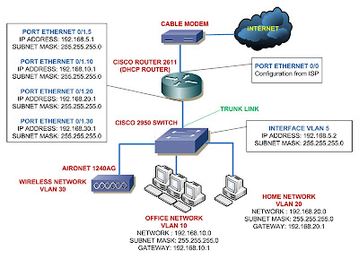
I'm going to add a Cisco switch, 2950 Cisco switch that is. And I'll be adding some VLANs to it, I'll separate the PCs in my LAN into four different networks.

  • VLAN 5 as the native VLAN - 192.168.5.0 network
  • VLAN 10 for the office - 192.168.10.0 network
  • VLAN 20 for the home - 192.168.20.0 network
  • VLAN 30 for wireless - 192.168.30 network
In network diagram view, you can see it like this:
This is just a very simple network diagram, but most SOHO networks are typically look like this, maybe with some additional switches here and there.

You can see above the details of the network with exception of the wireless network, I'll leave the wireless network configuration for later posts but still provide a VLAN for wireless connectivity.

Same with the previous posts, I'll do the configuration on series and hopefully in the end I can make a full Cisco home lab scenario for Cisco certification exam.

Read more!

7 Reasons to Choose Cisco for Home or SOHO Network


After building my own Cisco home lab, I feel very satisfied with how they perform for my LAN.

So let me poison your mind, I'm going to show you why I think home network geeks - like my self - and SOHO network should consider to replace the network devices they have now with Cisco networking devices.

Actually Cisco has an article called Why Enterprise Choose Cisco, but frankly I don't quite understand what they're trying to say so I figured 7 reasons that I can think of why choose Cisco for Home or SOHO network.

1. Cisco Certification

The number one reason is of course to smooth your way in passing Cisco Certification exams. You can get away not having Cisco home lab for the CCNA exam, but above that, especially if you don't have a direct access to the real Cisco devices, at least you need to rent Cisco lab.

2. Wide Range of Products

Not just apply to Cisco, every vendor has wide range of products to offer, routers, switches, VPN concentrators, wireless, firewalls, you name it.
But wouldn't it be nice to have a room in your home or SOHO with that cool Cisco logo on all of the devices.
Imagine clients walking down your office and see the network rack or at least the picture of it, and shockingly say what the heck is that???
Oh, that's just our small data center you reply.
Surely make your business seems reliable enough or what??

3. Scalability

This is what I really like from Cisco, you can easily upgrade everything, well almost everything in the devices.
Say you bought a 2611 router, the chassis only, and later you found out you need WAN connectivity, DSL connection, additional switch ports, VPN, and even Voice card for VoIP, etc.
You can just buy the modules and slide in to your router, not all of them of course, but as much as the router permits.
The complete reference for the modules supported by 2600 routers can be found here.

You can buy and upgrade the IOS according to your needs. Routers such as linksys also can be upgraded (the firmware), many third party firmwares are also available, but the Cisco IOS can do much more functionalities no doubt.

Need more power for the Cisco routers, no problem, you can always upgrade the RAM, now this is hard to do on average home usage routers. You can easily slide in a bigger RAM in the router just like PCs.
My default amount of 2611 RAM provides me a great connectivity to the internet compared to my old router.
You know if you connect lots of clients to the internet, the router maintains a NAT table and if the RAM is not enough it should affect the connectivity.

4. Managabililty

Having Cisco devices in your LAN is like being a tyrant in your own kingdom. You can pretty much do anything in it at your wish.
Kick out a client, limit the connection to nearly bytes per second and let them come to you and beg for mercy.
No no that's not me.. I think. I don't know about you but controling network devices from the CLI is like having an unlimited power over the LAN.
You can configure anything right from nothing and seeing it connects successfuly, I'm telling you nothing beats the feel of it.

5. Reliability

No question about reliability for Cisco devices. In fact I just knew that Cisco Systems Sets Guinness World Record with the World's Highest Capacity Internet Router.

Now get this, with the show version command in the device you can view the uptime right? how long the router is up and running without shutting down or reloading.
A company has a record of about 10+ years, 10 years, man, you should see it here or search in google for "cisco 10 years uptime".

6. Enterprise Class Features

Depends on the router capabilities and the IOS image you have, you can have an enterprise class features in your LAN.
Advance firewall system, Intrusion Detection System, Multicast handling, VoIP, all of that you can have just by upgrading your Cisco routers later when your company got bigger.

7. Cost

No, I'm not talking about the cost of buying Cisco devices, the price for the new ones are insane for home usage and SOHO. But you can always buy the used ones from ebay or other used Cisco resellers.
What I want to say is the cost that you can save if you bought Cisco devices. Return of Investment what smarter people would say.

So the reasons are good enough for you? If you're working in a SOHO you might be able to persuade the finance department to upgrade the network devices you have now.

But you're just students or a techies want to get deeply intimate with Cisco, how could you ever afford them.
If you really really want it why not? Take a look at me, I'm currently just about a quarter of century old, living in a country where you wouldn't dream of having a real live Cisco home lab.
And no, my Dad is not a millionaire, I bought the Cisco lab purely from my own income, one by one at a time, you just need to know what to buy and where.

Good luck

Read more!
25 October 2008

SNMP (Simple Network Management Protocol) for Cisco


When you've set up your Cisco devices, you might also want to monitor them. It's very inconvenient if you have to look at the lights blinking on your Cisco devices or logging to the devices and type in show ip interface brief just to see if the interfaces is running correctly.

To make monitoring network devices easier, the great people in network industry invented SNMP or Simple Network Management Protocol).

SNMP gives you great flexibility, you can allow a group of people to just monitor the network devices in your LAN (read-only rights) and allow other group for monitoring and making changes to the network devices (read-write rights).


The image above shows one of many networking tools that implements SNMP, this one if from solarwinds.
You can view in graphical form of CPU/memory usage, bandwidth usage, etc.

Some terms that you need to be familiar with in configuring SNMP:

GET

Gets are used to collect information from network devices, it's in a read-only mode. You need to configure a community string in a Cisco device so a network tool can identify it. Apply read-only rights so the users having this community string can only view information on network devices.

To set it in a Cisco device is very easy, just go to the global configuration mode and type in:

router (config)# snmp community public ro

The above command configure the router to have a community string of "public" with read-only rights.
You can also apply an access list to that community string.

Now that you have that community string, set this community string to the network tool so it can monitor the network device.

SET

The sets can be used to make changes to a network device such as shutting down an interface, etc.
Configuring sets is similar to the GET configuration, you only need to change the read-only rights to be read-write rights.

router (config)# snmp community private read-write

Since this command allows users who know the community string to be able to configure the network device, you should always apply an access list to the read-write command.

TRAPS

If the GETs and SETs are initiated by the admin, the traps are initiated by the network device itself.
This is very useful, in case an emergency situation pops out like an interface is shutdown, fan failure, etc. the device can immediately send message to a preconfigured destination.

Do this to send traps to host 192.168.1.10 with community string "public":

router (config)# snmp host 192.168.1.10 public


Read more!
21 October 2008

Configure Cisco Router to Work With Cable Internet - Part 4


Configuring NAT (Network Address Translation)

Continuing for the tutorial series of configuring Cisco router to work with cable internet, now we'll set the router to do NAT.

When connecting your router to the cable internet through cable modem, your router will receive a dynamic IP address from the ISP DHCP server according to the scenario.

While you only get one IP address from the ISP, you also need to connect more than one computer to the internet.
Plus the public IP address is different network with the private IP addresses in your LAN.

NAT can solve this problem, it stores the requesting private IP addresses in the address translation table of the router, translates every request from your LAN and forward it to the internet using the single public IP address.

Now NAT can be used in different scenario, but I'll save them for future posts, for now the NAT form that we'll use is many-to-one scenario of NAT.
Many private IP addresses translated to be one public IP address, some people call it overloading and/or Port Address Translation (PAT).

NAT Overload will assign a unique logical port number to every request from the LAN to the internet thus PAT.
For example, if you have a public IP address of 202.1.1.1, then for a request from the user of 192.168.1.20 in your LAN will be translated into 192.168.1.20:1720 for the incoming request to the router, and 202.1.1.1:1521.
This is how the router can identify which request goes to which device.

To configure it requires some steps, first lets see again how the network diagram looks like:

The image shows I only use one computer to connect to the internet, for now lets pretend I have a lot of computers in my LAN for internet connection.

You need to remember three basic steps for configuring NAT/PAT:
  1. Create access list to decide which private IP addresses are allowed to be translated by the router.
  2. Issue the NAT command to cooperate NAT with access list that we created and tell the router that we need to overload the requests if you use PAT.
  3. Identify which interface in the router that is connected to the LAN then issue ip nat inside command, and which interface is connected to the internet then issue ip nat outside command.
The steps are not necessarily be in that order, we can start with whichever step first. Here how you do those steps:

Create Access List

router> enable
router# configure terminal
router (config)# access-list 101 permit ip 192.168.1.0 0.0.0.255 any

Issue PAT command

router (config)# ip nat inside source list 101 interface Ethernet0/0 overload

Identify interfaces for ip nat inside and outside

router (config)# interface ethernet0/0
router (config-if)# ip nat outside
router (config-if)# interface ethernet0/1
router (config-if)# ip nat inside

That's it three easy to remember steps for configuring NAT/PAT, one last thing to do for connecting your router to the cable internet is configuring default route.

Configuring Default Route

I decided to include configuring default route into this post since I only have a simple network topology and we only need one line of command to configure the default route.
Here's how we do it, from the last command we jump back to the global configuration mode:

router (config-if)# exit
router (config)# ip route 0.0.0.0 0.0.0.0 ethernet0/0

What the above command does is to route all request that point to any ip address that the router doesn't know (0.0.0.0 0.0.0.0) to the ethernet0/0 interface.

If you have a static public IP address from the ISP then you can replace the ethernet0/0 with the IP address given by the ISP.

That concludes the tutorial series for connecting your router to the internet cable, thank you for following the series, and please give me feedback about my posts.

Please read also:
Configure Cisco Router to Work With Cable Internet - Part 1
Configure Cisco Router to Work With Cable Internet - Part 2
Configure Cisco Router to Work With Cable Internet - Part 3

Read more!

18 October 2008

Configure Cisco Router to Work With Cable Internet - Part 3


Setting Cisco Router as DHCP Server

This option really is optional if you want to set Cisco router to work with cable internet, but this is a good chance to add your skill in configuring Cisco devices.

From the previous post, you know how to configure your router's interface to accept IP address from DHCP server.
Now it's time to configure your router as DHCP server.

Once again you need to make sure your Router IOS image support the DHCP server feature if not then the command won't be available.

To set a DHCP server, you will configure a pool of network IP addresses that you want to give out to the clients (PC, printer, NAS, etc).
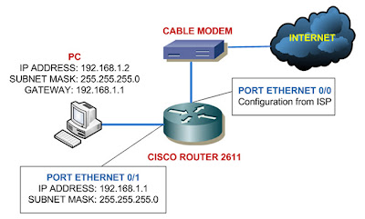
As shown on the image in the previous post, I want to give out the IP addresses from the network 192.168.1.0.

First thing you need to configure is to exclude the IP addresses that you dont want to give out.
For example, I've configured the router interface 0/1 to be 192.168.1.1, then I need to exclude 192.168.1.1 so the router won't give out this address.
You can configure the exclusion in the router's global configuration mode:

router> enable
router# configure terminal
router (config)# ip dhcp excluded-address 192.168.1.1

This command is very useful especially if you need to exclude a range of IP addresses, if you need to exclude say 192.168.1.1 until 192.168.1.10 you can do it like this:

router (config)# ip dhcp excluded-address 192.168.1.1 192.168.1.10

After the ip dhcp excluded-address we give the low IP address and the high IP address, this way your router not give IP addresses from 192.168.1.1 to 192.168.1.10, the router will start giving out address from 192.168.1.11 and so on.

Next thing to do is creating a pool of addresses, when issuing the ip dhcp pool, you'll be taken to the dhcp configuration mode where you can set the additional parameters beside the ip address and subnet mask to the clients.
In this example I want to make a pool with the name of HOME_CLIENTS

router> enable
router# configure terminal
router (config)# ip dhcp pool HOME_CLIENTS
router (dhcp-config)# network 192.168.1.0 255.255.255.0
router (dhcp-config)# default-router 192.168.1.1
router (dhcp-config)# import all

At the third line above you can see the configuration command of a pool with the name HOME_CLIENTS.

Fourth line shows that the pool HOME_CLIENTS will give out the addresses in the network 192.168.1.0, with the exception of the addresses in the ip dhcp excluded-address 192.168.1.1 that I showed you previously.

Fifth line tells the clients should be given a default gateway address of 192.168.1.1 (the router's IP address).

The sixth line is the one important thing for configuring DHCP server in cable internet environment.
The import all command tells the router to give out other configuration received from the ISP cable internet DHCP server to the clients in the LAN.
For example, most ISP will give the DNS servers IP addresses from their DHCP server and this configuration might change depends on the ISP, so you definitely want to give this configuration out to the clients.

If you have your own DNS server in the LAN, you can tell the clients to use this DNS server using the following command:

router (dhcp-config)# dns-server 192.168.1.2 192.168.1.3

The above command will send out DNS server address of 192.168.1.2 and 192.168.1.3 to the clients.

You can also configure the router to use the above DNS server using the following command in the global configuration mode:

router (config)# ip name-server 192.168.1.2 192.168.1.3

You can get more information on Cisco IOS DHCP and DNS commands in the cisco site, please click here to go there.

Please read also:
Configure Cisco Router to Work With Cable Internet - Part 1
Configure Cisco Router to Work With Cable Internet - Part 2
Configure Cisco Router to Work With Cable Internet - Part 4

Read more!

17 October 2008

Configure Cisco Router to Work With Cable Internet - Part 2


Setting IP Address to Cisco Router's Interfaces

We need to first set the IP address of the router's interfaces to begin configuring Cisco router to work with cable internet.

If you configure the router for the first time, connect to it using the console cable.

WARNING!!!

Not every Cisco IOS image supports the commands below, make sure your router's IOS support the commands, please read here first. If your image doesn't support it, the commands wont work.
Or check the features of your IOS image here.

Make sure your Cisco IOS image supports DHCP features (client/server).

As I said in the last post, the interface ethernet 0/0 is connected to the cable modem and interface ethernet 0/1 connected to my PC like shown below:


Ethernet 0/0 is using configuration got from the ISP so we'll set it to receive IP address from ISP's DHCP server. Always remember to give no shutdown command on the interface:

router> enable
router# configure terminal
router (config) # interface ethernet 0/0
router (config-if)# ip address dhcp
router (config-if)# no shutdown

Now to set the Ethernet 0/1 port as the picture above, we can just jump right to the interface 0/1 configuration mode:

router (config-if)# interface ethernet 0/1
router (config-if)# ip address 192.168.1.1 255.255.255.0
router (config-if)# no shutdown

You have successfully configure IP addresses to your interfaces, you can check it using the following command:

router# show ip interface brief


InterfaceIP-AddressOK?MethodStatusProtocol
Ethernet0xxx.xxx.xxx.xxxYESDHCPupup
Ethernet1192.168.1.1YESNVRAMupup


The show ip interface brief is a very useful command, you would want to use it to check the status of your interfaces.

The interface column shows you all the interfaces you have, the IP-Address is of course shows the addresses of the respective interfaces.

The Method column shows whether the addresses given by a DHCP server or you configured it yourself (stored in NVRAM) or it can also shows TFTP - configuration from TFTP server.

When the status column is showing down then it indicates there is a problem with OSI Layer 2.
The protocol will show up if the interfaces are physically connected to other devices, if not they will show as down (a problem with the OSI Layer 1).
And there's also another state of the status column -administratively down - it means the interface is shutdown.
This is the most likely question you'd get in the CCNA exam.

You can read further about show ip interface brief command here.

When you finished this configuration, your router will be receiving IP address on interface 0/0 from DHCP server of the ISP, and the interface 0/1 will be ready to communicate with network 192.168.1.0

Please read also:
Configure Cisco Router to Work With Cable Internet - Part 1
Configure Cisco Router to Work With Cable Internet - Part 3
Configure Cisco Router to Work With Cable Internet - Part 4

Read more!

16 October 2008

Configure Cisco Router to Work With Cable Internet - Part 1


If you just bought your first used Cisco router, I bet one thing you want to immediately do is connecting the Cisco router to the cable internet.
I know I did, I have cable internet for my home network. Previously I used Linksys router to get my LAN connected to the internet.

Configuring Cisco router to connect to the cable internet is easy work, even if you know only the basic configuration stuff in Cisco.

I need to warn you that this configuration will be in series or else this configuration will be a very long post. And also this series will be a good chance to learn some aspects in configuring Cisco router.

All you need to do is to set the IP address of the interfaces, set the router as a DHCP server if you want it, configure NAT, and the last thing is routing. Very simple indeed.

I'm only going to show you to get your router up and running, I wont discuss about access list and other fancy stuff - that's for the next posts.
Also the devices involve in this tutorial is only the Cisco 2611 router, Motorola cable modem, and my PC. If you want to use other Cisco devices you might need to do more configuration.

In this Part 1, I'm going to review about the concept of this configuration, please look at the topology image below:

Configure IP Address of the Router's Interfaces

The router will get the ip configuration from DHCP server of the ISP, the Ethernet 0/0 port I use as the exit point to the internet.
The Ethernet 0/1 will be the port where my computer is connected. I'm going to set private IP address as the gateway for the computer.

Setting IP address of the interfaces is definitely a topic in the CCNA exam.

Configure the Router as DHCP Server

In this example I'm using the router as DHCP server, giving IP addresses to the computer along with other configuration such as subnet mask, gateway address, and the dns server ip address.

You won't be tested about setting router as DHCP Server in the CCNA exam, it will show up in the CCNP exam.

Configure NAT (Network Address Translation) in The Router

NAT is a powerful concept, you have one public IP address given by the ISP and also private IP addresses in your LAN.

What NAT will do is translate all your private IP address into the public IP address. If you're using overload - one public IP address used by many private IP address - the private IP address is converted into logical ports.

For example, if you got public IP address of 10.1.1.1, then the form of the translation might be like this 10.1.1.1:3000

NAT is also a topic in the CCNA exam and one of the thoughest that is.

Configure Routing

This example only shows the basic static routing, the router will send all request from the client (from port Ethernet 0/1) to the port Ethernet 0/0.

You surely want to learn about routing for the CCNA exam.

Please read also:
Configure Cisco Router to Work With Cable Internet - Part 2
Configure Cisco Router to Work With Cable Internet - Part 3

Configure Cisco Router to Work With Cable Internet - Part 4
Read more!
