Showing posts with label how to. Show all posts

02 December 2008

Configuring SSH for Cisco


In the CCNA level, we only know how to connect to Cisco devices using console connection and telnet connection.

We know that no one can tap on the console connection since it's directly connected to the Cisco device, but different story for the telnet connection.
Anyone can tap messages from the telnet session.

All messages send in clear text, so it's dangerous to leave default communication with Cisco devices just using telnet.

We can use SSH for secure connection to the Cisco devices. The SSH will encrypt all messages going from your computer to the Cisco devices.

First you're going to need Cisco IOS image that support SSH or IPSec, DES, or 3DES. How would you know that. Well you can just issue the following command:

router> ena
router# show ip ssh
% Invalid input detected at '^' marker.

If it's showing % Invalid input detected at '^' marker., then the IOS does not support SSH.

Now start with the configuration, you have to define a hostname for the Cisco device, and also the domain name for it.
In this example I use hostname of "netrouter" and domain name of "ciscolab.home".

router (config)# hostname netrouter
netrouter (config)# ip domain-name ciscolab.home

Next is to generate the rsa keypair used for the encryption, your device name plus the domain name will be the name of the key.
The modulus is the length of the key, the default value is 512 bits, Cisco recommends a length of 1024 bits.

netrouter (config)# crypto key generate rsa

The name for the keys will be: netrouter.ciscolab.home
Choose the size of the key modulus in the range of 360 to 2048
for your General Purpose Keys. Choosing a key modulus greater than
512 may take a few minutes.

How many bits in the modulus [512]: 1024
% Generating 1024 bit RSA keys ...[OK]

You can also configure some additional parameters for the SSH Connection:

netrouter (config)# ip ssh authentication-retries 5
netrouter (config)# ip ssh time-out 120
netrouter (config)# ip ssh version 2

The first command sets the number of retries if you failed or mistyped the username and password.
The second command sets the time out, the time required to enter the username and password in seconds.
The last command sets the version you want to use for the SSH.

Now we have generated keypair for the encryption, how will the Cisco device authenticates the users coming with SSH connection.
You can either use a AAA server like RADIUS or TACACS+ or you can just use the Cisco device local username and password. For now I'd just use local authentication, first set the username and password then configure the device to accept local authentication for the line vty connections.

netrouter (config)# username Cisco password homelab
netrouter (config)# line vty 0 4
netrouter (config-line)# login local

By now you have successfully configure SSH for Cisco, lets try the SSH, you can use putty for SSH connection, the default port for SSH is 22, you can use other port if you want by issuing ip ssh port 2000 from the global configuration mode.
Change the 2000 with other port ranging from 2000 to 10,000.

Here I'm using the default terminal from Macintosh:

Macintosh:~ krishananda$ ssh Cisco@192.168.1.1
Cisco@192.168.1.1's password:

netrouter>

There, the SSH is working. But the telnet session is also still working, now I want to restrict the Cisco device to only accept SSH connection and deny telnet connection.

WARNING!!!

Do not disconnect from your current connection especially if it's telnet session, in case you messed up with the configuration, you can always undo the changes.


netrouter (config)# line vty 0 4
netrouter (config-line)# transport input ssh

Now if I try to connect using telnet, the router will deny it:

Macintosh:~ krishananda$ telnet 192.168.1.1
Trying 192.168.1.1...
telnet: connect to address 192.168.1.1: Connection refused
telnet: Unable to connect to remote host

Hope this is useful for you.

TIPS:

If you're using macintosh, and you change the rsa key by issuing crypto key generate rsa again on the same device,
Your mac will deny the SSH connection, telling you a warning about a man in the middle attack or the rsa key has changed.
All you need to do is open your text editor, open a file /users/yourname/.ssh/known_hosts
wipe out the content of known_hosts file and save.
That should do the trick.


Read more!

12 November 2008

Configuring WPA and WPA2 on Cisco Aironet


The last post I talked about configuring WEP authentication on Cisco Aironet wireless access point.
Now I want to configure WPA and WPA2 to give more strength in the wireless security.

Just for a note I put an image of padlock on the last post and now I give a picture of a vault to give the image of stronger security.
You know what I mean, padlock versus vault, oh just forget it.

Back to the topic, when first posting about WEP I said that WEP encryption is weak, you better use encryption like WPA and WPA2.

WPA gives better key management and stronger cipher encryption. For those who don't know about cipher, it's kinda algorithm for encryption and decryption, we'll be configuring the cipher when dealing with WPA and WPA2. WPA uses what is called TKIP or Temporal Key Integrity Protocol for the cipher encryption.

WPA2 is even better than WPA, it uses a stronger encryption called AES or Advanced Encryption Standard, it creates fresh sessions key so every packet sent are encrypted with different key.

One other thing to know, the WPA and WPA2 come with two flavors, the Personal and Enterprise. In enterprise mode we need to have authentication server such as RADIUS, I don't have RADIUS server currently so I'll skip to the Personal mode instead.
The personal mode of WPA and WPA2 have what is called WPA-PSK the WPA Pre-Shared Key, we have to configure the WPA-PSK on both the Access Point and the clients.

So get on to the configuration of WPA first for my SSID Guest on VLAN 40:

1240AG> enable
1240AG# configure terminal
1240AG (config)# interface dot11radio 0
1240AG (config-if)# encryption vlan 40 mode ciphers tkip
1240AG (config-if)# ssid Guest
1240AG (config-if-ssid)# vlan 40
1240AG (config-if-ssid)# authentication open
1240AG (config-if-ssid)# authentication key-management wpa
1240AG (config-if-ssid)# wpa-psk ascii your-key-here

That's it you've successfully configured WPA on Cisco Aironet Wireless Access Point. Just configure the ciphers to tkip, set the authentication to open, use the wpa key management and the great thing in WPA is that we can set ascii characters as the key instead of hexadecimal like we did on configuring WEP.

The difference of WPA with WPA2 configurations is just some small things. We have to set the ciphers to AES and the key management to WPA version 2. Let's get started to configure WPA2 for my SSID Admin on VLAN 30:

1240AG> enable
1240AG# configure terminal
1240AG (config)# interface dot11radio 0
1240AG (config-if)# encryption vlan 30 mode ciphers aes-ccm
1240AG (config-if)# ssid Admin
1240AG (config-if-ssid)# vlan 30
1240AG (config-if-ssid)# authentication open
1240AG (config-if-ssid)# authentication key-management wpa version 2
1240AG (config-if-ssid)# wpa-psk ascii your-key-here

Don't forget to check out how to set up Wireless Network and the SSID on my last posts. Cheers.

Read more!

10 November 2008

Configuring WEP Authentication on Cisco Aironet


The wireless network you installed for your LAN can mean that you are directly exposing your network to the public.

Anyone can use a wireless sniffer and view all the traffics going between the wireless access point and the clients. That's why you need to add security in your wireless LAN.

This post will talk about WEP or Wired Equivalent Privacy, the name states that your wireless network will be as safe as your wired network but not in reality.
There are many WEP decryption tools available out there. Just capture some packets using wireless sniffer and use the the decryption tool to find out the WEP key.

So we know the WEP is not secure, nevertheless I want to show how to configure WEP authentication for Cisco Aironet wireless access point.

WEP uses 40 bits encryption key (10 hexadecimal characters) or 128 bits (26 hexadecimal characters).
Don't get a false sense of security with the length of the encryption, the longer the encryption key just mean the more packets you need to capture and more time to decrypt them.

There are two types authentication for security according the IEEE 802.11 committee, the shared-key and open authentication.

In a shared-key authentication, the access point will send a challenge packet to the client and the client must encrypt the packet with with the right key (WEP key) then return it to the access point.
This method is not secure since everything sent in clear text.

The other method is open authentication, just like the name the authentication is open or you can say no authentication required.
But when open authentication used with the WEP, the WEP key will be used to encrypt all data before sending them.

I have to admit, I get a little confused when first time configuring authentication in Cisco Aironet wireless access points since no one thought me so I had to browse all the configuration examples.

It's easier to use the web interface of the access point, but I want to configure it through CLI.
To configure WEP authentication you should do this by entering the dot11radio interface:

1240AG> enable
1240AG# configure terminal
1240AG (config)# interface dot11radio 0

Create the SSID and associate it with VLAN if you haven't done it:

1240AG (config-if)# ssid Guest
1240AG (config-if-ssid)# vlan 40
1240AG (config-if-ssid)# authentication open
1240AG (config-if-ssid)# exit

Configure the WEP authentication:

1240AG (config-if)# encryption vlan 40 mode wep mandatory
1240AG (config-if)# encryption vlan 40 key 1 size 128bit 12345678901234567890123456 transmit-key

The above first command tell the Cisco Aironet to do WEP encryption on vlan 40 (SSID Guest) and set it as mandatory.
If you replace mandatory with optional, the use of WEP encryption depends on the client configuration, they can choose to encrypt the packets or not.

The second command tells the access point to use the WEP encryption key of 128 bit with the above 26 characters key. You can use whatever key you choose as long as it is hexadecimal characters (0-9 and A-F).

Don't forget to set up the access point as I did on the last post.

Read more!

08 November 2008

Configuring Cisco Aironet in Home Lab - Part 2


Now it's time to configure Cisco Aironet Wireless Access Point for Cisco home lab.

What I'm going to do first is to configure the connectivity between the Cisco Aironet 1240AG wireless access point to the Cisco 2950 switch.

Here's the closer look of the network diagram of the wireless access point and the switch:


The network will be using VLAN 5 (192.168.5.0 network) as the native VLAN and the rest of the VLANs will be used for the SSIDs.

There's an interface called BVI or Bridge-group Virtual Interface, what this interface does is bridge all of the interfaces in the access point - the wired and wireless interfaces - so you can use the interface BVI IP address to manage all of those interfaces.

In Cisco Aironet 1240AG wireless access points, you have 1 interface fast ethernet port, 1 console port, 1 dot11radio 0 for the 802.11G, and 1 dot11radio 1 for 802.11A.

In this configuration I only going to configure the dot11radio 0 for the 802.11G wireless network since I only have the antennas for the 802.11G.
You can configure both 802.11A and 802.11G if you want.

First we configure the interface BVI 1 IP address:

1240AG> enable
1240AG# configure terminal
1240AG (config)# interface bvi 1
1240AG (config-if)# ip address 192.168.5.3 255.255.255.0
1240AG (config-if)# no shutdown

Now set the native VLAN (VLAN 5) to the wireless access point, we have to configure the native VLAN on both of the fastethernet sub interface and the dot11radio 0 sub interface:

1240AG (config)# interface fastethernet 0.5
1240AG (config-if)# encapsulation dot1q 5 native
1240AG (config-if)# interface dot11radio 0.5
1240AG (config-if)# encapsulation dot1q 5 native

Next is to set up the SSID starting from SSID for admin and associate it with VLAN 30.
We need to configure the SSID on the dot11radio 0 interface first then configure the VLAN on the dot11radio 0.30 sub interface and fast ethernet 0.30 sub interface.
Also I set up the SSID for open authentication first.

1240AG (config)# interface dot11radio 0
1240AG (config-if)# ssid ADMIN
1240AG (config-if-ssid)# vlan 30
1240AG (config-if-ssid)# authentication open
1240AG (config-if-ssid)# end

1240AG (config)# interface fastethernet 0.30
1240AG (config-subif)# encapsulation dot1q 30
1240AG (config-subif)# bridge-group 30

1240AG (config-subif)# interface dot11radio 0.30
1240AG (config-subif)# encapsulation dot1q 30
1240AG (config-subif)# bridge-group 30

The bridge-group command allows you to group interfaces and bridge nonrouted traffic among the interfaces.
In this example traffic from dot11radio 0.30 sub interface to fastethernet 0.30 sub interface and vice versa.

Note: If you configure the SSID on the global configuration mode, the SSID will be both in the dot11radio 0 and 1.

Do the same with the SSID for guest and associate it with VLAN 40:

1240AG (config)# interface dot11radio 0
1240AG (config-if)# ssid GUEST
1240AG (config-if-ssid)# vlan 40
1240AG (config-if-ssid)# authentication open
1240AG (config-if-ssid)# end

1240AG (config)# interface fastethernet 0.40
1240AG (config-subif)# encapsulation dot1q 40
1240AG (config-subif)# bridge-group 40

1240AG (config-subif)# interface dot11radio 0.40
1240AG (config-subif)# encapsulation dot1q 40
1240AG (config-subif)# bridge-group 40

Next step is to configure the switch port connected to the wireless access point as a trunk port with native VLAN 5.
I already posted about how to do this on the last post.

Also if you are going to use dynamic IP address, make sure you have configured router as DHCP server that serving clients for VLAN 30 and 40.

Right now if you have no problem pinging the switch and router from the wireless access point, your access point is broadcasting SSID and giving IP address from router for any client joining the SSID.

The SSIDs are not secure since they use open authentication, next time I'll configure it with stronger authentication.

Read more!

07 November 2008

Configuring Cisco Aironet in Home Lab - Part 1


I've configured my Cisco home lab with a router that connects to cable internet and a switch with VLANs.
Now it's time to add a new device to the Cisco home lab, a Cisco Aironet 1240AG wireless access point for wireless connection.

And by the way, the image on the left is not an official logo from Cisco or anything, I just made that up.

I won't configure anything fancy this time, only give basic administration configuration and set up an open SSIDs also associate the SSIDs to VLANs.

Since I want to configure two SSIDs - one is free for all SSID with no authentication and the other one with authentication - for the wireless network, I need to configure additional VLAN on the switch.

I have already the VLAN 30 for the wireless network and want to add VLAN 40, so in total there would be 5 VLANs in my Cisco home network lab.

I made a network diagram with Cisco Aironet 1240AG wireless access point added in the picture below:

So lets start the configuration on the next post, there are some steps to complete this Cisco home lab network diagram if you haven't done so.

Starting from the wireless access point I'm going to configure the basic administration configuration such as the access point's management IP address, SSIDs and associate them to VLANs, optionally configure the authentication security options for the SSIDs, and establish trunk connection to the switch.

For the switch I'll configure VLANs and the trunk connection to the access point and the router.

Last in the router I'll configure interVLAN routing, DHCP server for each VLAN, and other configurations like I've posted before.

Read more!

30 October 2008

Adding Switch to Cisco Home Lab - Part 5


Configure Router as DHCP Server for VLANs

Now this part of configuration is the most fun part of all. I just love the way that one router accepts requests from clients on different VLANs (with different subnets), and the router gives away the addresses based on what VLAN a client resides.

That's just cool, your average home usage routers can't do this kind of stuff, most of the average home usage routers can do is just give away IP addresses for one network.

At the previous post, I posted about how to make a router to be DHCP server. Now this post is similar but I'm going to make the router to give away IP addresses for clients on different networks.

The configuration is also the same, but now I'm going to make several IP DHCP pool. The amazing thing is that the router can differentiate each client request for IP address.

The router listens to the requests, which request comes from which sub interface (subnet or VLAN).
Then the router takes the available IP address from the DHCP pool and tells the client that it's now using this IP address.

At this example I'm using four networks in my local area network. I won't be giving away the addresses for the VLAN 5 since I'm only going to assign the IP addresses for management purpose only - I'll assign the addresses statically on the networking devices.
The 3 networks left, the VLAN 10, 20, and 30 IP addresses are configured using DHCP server.

Same as before, you need to exclude the IP addresses that you don't want to give out through DHCP. I conserve the first ten addresses for each network, I probably need it for something else in the future.

router> enable
router# configure terminal
router (config)# ip dhcp excluded-address 192.168.10.1 192.168.10.10
router (config)# ip dhcp excluded-address 192.168.20.1 192.168.20.10
router (config)# ip dhcp excluded-address 192.168.30.1 192.168.30.10

Now the DHCP will give out addresses to the clients starting from XXX.XXX.XXX.11

Next is to configure the DHCP pools for respective VLANs:

router (config)# ip dhcp pool OFFICE
router (dhcp-config)# network 192.168.10.0 255.255.255.0
router (dhcp-config)# default-router 192.168.10.1
router (dhcp-config)# dns-server xxx.xxx.xxx.xxx xxx.xxx.xxx.xxx

router (config)# ip dhcp pool HOME
router (dhcp-config)# network 192.168.20.0 255.255.255.0
router (dhcp-config)# default-router 192.168.20.1
router (dhcp-config)# dns-server xxx.xxx.xxx.xxx xxx.xxx.xxx.xxx

router (config)# ip dhcp pool OFFICE
router (dhcp-config)# network 192.168.30.0 255.255.255.0
router (dhcp-config)# default-router 192.168.30.1
router (dhcp-config)# dns-server xxx.xxx.xxx.xxx xxx.xxx.xxx.xxx

You can set the dns-server option to point to up to 6 dns servers.
The default-router command tells the clients to set the ip default gateway to point to the router's sub interface.

At this point, if you can ping all the sub interfaces of the router from the switch, the router will give IP addresses for requests coming from the clients for DHCP service.

The router differentiates the requests like this, if a request coming from the sub interface ethernet 0/1.10, then the router will give the IP address according to the ip address on that interface (192.168.10.0 network).

After this you need to configure the router for internet connection, if you haven't done it before.
Remember to apply access-list that allows all networks you have in the LAN to be translated by the NAT.
Read more!

29 October 2008

Adding Switch to Cisco Home Lab - Part 4


Configure Router for InterVLAN routing

If you only configure VLAN on the 2950 or other layer 2 switches, the clients can only communicate with other clients within the same VLAN.
If you want them to be able to communicate with other clients on different VLANs, then you need to configure a router for interVLAN routing.

Configuration of router for interVLAN routing often called router on a stick. The reason is the clients that want to communicate with other clients on different VLANs need to go through the router first and the router will route the packets to the appropriate VLANs back through the same line.

The disadvantage of this is that single line going to the router will be filled by requests from one VLAN going to other VLAN, and the router will be set for handling the routing for this.

No problem for the small LAN, but if you have a huge number of clients, you need to consider using Layer 3 or multilayer switches (Cisco Catalyst 3550 series or above) for interVLAN routing.

The concept of layer 3 switch routing is something that you'd find on the CCNP level, not the CCNA.
I don't have layer 3 switch, the cheapest one I can find in my local area is more than $600 yikes. But the configuration is so easy, I'll only want to give you some snippets later.

For now lets configure the router to do interVLAN routing.

We know that routers have limited amount of physical interfaces right? The 2611 have a default of 2 ethernet interfaces.
One interface is going to the internet and the other is supposedly connected to the internal LAN.
How come one interface can handle multiple VLANs a.k.a. multiple networks with different subnets.

There's a genius way to get around this, that is by using logical sub interfaces. That one port can be logically devided into many sub interfaces.
Each sub interface will handle one VLAN/subnet.

NOTE:

Previously the interVLAN routing can only be done by routers with Fast Ethernet interfaces (100 Mbps) and not intended for Ethernet interfaces (10 Mbps) due to small bandwidth consideration. But now we can configure it on the ethernet ports also.

Before configuring the router, lets see again how the network diagram looks like:

So we need to define four sub interfaces and the respective IP addresses, we also need to define the VLAN assigned to the sub interface using encapsulation dot1q VLAN_NUMBER, where the VLAN_NUMBER is the VLAN ID for the sub interface.
You need to define the VLAN first on the sub interface, then you can assign IP address there.
You don't need to assign IP address for the main interface ethernet 0/0 but do no shutdown and the sub interfaces will automatically apply the same no shutdown.
here's how we configure them:

router> enable
router# configure terminal
router (config)# interface ethernet0/0
router (config-if)# no ip address
router (config-if)# no shutdown
router (config-if)# interface ethernet0/0.5
router (config-if)# interface ethernet0/1.5
router (config-subif)# encapsulation dot1q 5
router (config-subif)# ip address 192.168.5.1 255.255.255.0
router (config-subif)# interface ethernet0/1.10
router (config-subif)# encapsulation dot1q 10
router (config-subif)# ip address 192.168.10.1 255.255.255.0
router (config-subif)# interface ethernet0/1.20
router (config-subif)# encapsulation dot1q 20
router (config-subif)# ip address 192.168.20.1 255.255.255.0
router (config-subif)# interface ethernet0/1.30
router (config-subif)# encapsulation dot1q 30
router (config-subif)# ip address 192.168.30.1 255.255.255.0

You can give sub interface number up to 4294967295, the reason is it gives you the flexibility on naming the sub interface to match the VLAN ID. You can easily identify the sub interface e0/1.5 is for VLAN 5 and so on.

Oh, don't forget to do the no shutdown command on the main interface ethernet 0/1, it will also do no shutdown for the sub interfaces.

Now if you can successfully ping the interface VLAN 5 on the switch (192.168.5.2 in this example) then you are done configuring the router for interVLAN routing.

For configuring interVLAN routing on Layer 3 switches you have to make interface VLAN for every VLAN that you want to route and give them IP addresses.

Layer3Switch> enable
Layer3Switch# configure terminal
Layer3Switch (config)# interface VLAN 5
Layer3Switch (config-if)# ip address 192.168.5.1 255.255.255.0
Layer3Switch (config-if)# no shutdown

Do this for every VLAN that you want to route, you don't need to configure sub interfaces on the router.
The layer 3 switch will do the routing for the VLANs without ever need to send anything to the router first.
But you need to activate the ip routing feature on the switch first, if it's not already activated using:

Layer3Switch (config)# ip routing

Very simple right?

Last things left is to configure the router for additional configuration, DHCP server for each subnet, connect to the cable internet, and other details on the next post.

Read more!

28 October 2008

Adding Switch to Cisco Home Lab - Part 3


Assigning Switch Ports to VLANs

After configuring VLANs on Cisco switch, now we need to assign the switch ports to VLANs.

We need to assign which ports should be in which VLAN, remember VLAN = broadcast domain = subnet.
So before making your own VLANs, consider the IP addressing scheme and which computer should be in which broadcast domain or network.

Next step is to configure the trunk port to connect to the router and access port to connect the switch ports to our clients' PCs or other network devices.

The trunk port is needed to carry all VLANs or selected VLANs (you can decide which VLANs are allowed to cross the trunk link) in one port and the native VLAN is assigned to "tag" untagged frames with the ID of the native VLAN.
You should also configure trunk if you want to connect a switch to another switch, you have to configure trunk port on both switches.

For the access port, one access port can only be a member for 1 VLAN, anything plug in to the access port will be assign with the configured VLAN ID.

You need to remember though, the devices attaced to the switch ports don't know anything about VLAN, it is only something the switch knows.
Before a frames are sent to the clients, the VLANs tags are stripped from the frames.

In this example I configure the FastEthernet port 0/1 to be the trunk port that connects to the router.

C2950> enable
C2950# configure terminal
C2950 (config)# interface fa0/1
C2950 (config-if)# switchport mode trunk

At this point you already configured the port FastEthernet or fa 0/1 to be trunk port.
There are two encapsulation method for trunking, the ISL which is proprietary method from Cisco - only for Cisco devices and the 802.1Q or dot1q for short which is the multi-vendor encapsulation method.

Since the 2950 switches only support dot1q method you don't need to define it again but if your switch support both methods then you need to configure it using switchport trunk encapsulation dot1q or you can replace the dot1q with isl if you want to use ISL.

Next is to define the native VLAN and if you want to, you can define which VLANs are allowed to cross that trunk port:

C2950 (config-if)# switchport trunk native vlan 5
C2950 (config-if)# switchport trunk allowed vlan add 5, 10, 20, 30

You can add or remove vlans on the trunk port, by default the trunk will carry all VLANs.

Finished with the trunk port configuration, now we assign ports to the VLANs we created. You can assign the ports one by one like this:

C2950 (config)# interface fa0/2
C2950 (config-if)# switchport mode access
C2950 (config-if)# switchport access vlan 10

Or you can define a range of interfaces at once, say I want to configure port 0/2 to 0/8 as the access port for VLAN 10, then I just have to do this:

C2950 (config)# interface range fa0/2 - 8
C2950 (config-if-range)# switchport mode access
C2950 (config-if-range)# switchport access vlan 10

Do the same thing with the VLAN 20 - the home network VLAN:

C2950 (config)# interface range fa0/9 - 16
C2950 (config-if-range)# switchport mode access
C2950 (config-if-range)# switchport access vlan 20

Very handy command right?

One trick I can give you, if you want to configure some ports that are not in sequential order, like you want to configure port 2 to 5 and 10 to 15 and port 24, you can do it like this:

C2950 (config)# interface range fa0/1 - 5, fa0/1 - 15, fa0/24

There, you successfully created access ports for VLAN 10 and 20. For the VLAN 30 or the VLAN used for wireless network, I need to safe it for another time since configuring wireless network with Cisco devices takes some tricks.

Now we're done with the Cisco switch configuration, next thing to do is configuring the router to accept VLANs and be DHCP server for all the networks.

Read more!

Adding Switch to Cisco Home Lab - Part 2


Configuring VLANs

I'll start the configuration of adding switch to my Cisco home lab by configuring the switch first. At the previous tutorial series, I posted about how to connect Cisco router to cable internet, and now here's how the network will look like again when added a switch to it:

The network will have 4 VLANs, with the VLAN 5 acting as the native VLAN.
By default, the native VLAN of Cisco switches is VLAN 1, you might want to change the native VLAN from VLAN 1 to other VLAN since there a security concern about this.

You can read a nice article about native VLAN security concern from cisco.

In 2950 switches, you have to type in these commands to create VLANs:

C2950> enable
C2950# configure terminal
C2950 (config)# vlan 5
C2950 (config-vlan)# name MANAGEMENT
C2950 (config-vlan)# vlan 10
C2950 (config-vlan)# name OFFICE
C2950 (config-vlan)# vlan 20
C2950 (config-vlan)# name HOME
C2950 (config-vlan)# vlan 30
C2950 (config-vlan)# name WIRELESS

You can verify that you successfully created the VLANs by issuing this command:

C2950# show vlan

Now to set the VLAN 5 as the native VLAN and assign it to be the native VLAN, we should do this:

C2950 (config)# interface VLAN 5
C2950 (config-if)# ip address 192.168.5.2 255.255.255.0
C2950 (config-if)# no shutdown

By issuing the no shutdown command, the VLAN 1 will be automatically shutdown and replaced by the VLAN 5.
Assigning an IP address to the VLAN other than VLAN 1 will make that VLAN as management VLAN so your switch can be accessible for configuration using telnet.
You can only alter the Native VLAN from VLAN 1 to other VLAN but you can't delete the VLAN 1.

Next thing you need to do is assigning those VLANs to the switch's ports.

Read more!

27 October 2008

Adding Switch to Cisco Home Lab - Part 1


So I was sitting and thinking about what to post next in my blog, and hey why not continuing on the last posts about setting up Cisco home lab.

The network topology might not be the best topology for CCNA home lab, but the configuration should be similar with any other topologies.

Let's take a look at the last network topology where I connected 2611 router to the cable internet:
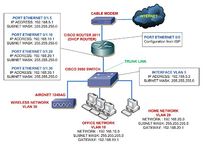
I'm going to add a Cisco switch, 2950 Cisco switch that is. And I'll be adding some VLANs to it, I'll separate the PCs in my LAN into four different networks.

  • VLAN 5 as the native VLAN - 192.168.5.0 network
  • VLAN 10 for the office - 192.168.10.0 network
  • VLAN 20 for the home - 192.168.20.0 network
  • VLAN 30 for wireless - 192.168.30 network
In network diagram view, you can see it like this:
This is just a very simple network diagram, but most SOHO networks are typically look like this, maybe with some additional switches here and there.

You can see above the details of the network with exception of the wireless network, I'll leave the wireless network configuration for later posts but still provide a VLAN for wireless connectivity.

Same with the previous posts, I'll do the configuration on series and hopefully in the end I can make a full Cisco home lab scenario for Cisco certification exam.

Read more!

21 October 2008

Configure Cisco Router to Work With Cable Internet - Part 4


Configuring NAT (Network Address Translation)

Continuing for the tutorial series of configuring Cisco router to work with cable internet, now we'll set the router to do NAT.

When connecting your router to the cable internet through cable modem, your router will receive a dynamic IP address from the ISP DHCP server according to the scenario.

While you only get one IP address from the ISP, you also need to connect more than one computer to the internet.
Plus the public IP address is different network with the private IP addresses in your LAN.

NAT can solve this problem, it stores the requesting private IP addresses in the address translation table of the router, translates every request from your LAN and forward it to the internet using the single public IP address.

Now NAT can be used in different scenario, but I'll save them for future posts, for now the NAT form that we'll use is many-to-one scenario of NAT.
Many private IP addresses translated to be one public IP address, some people call it overloading and/or Port Address Translation (PAT).

NAT Overload will assign a unique logical port number to every request from the LAN to the internet thus PAT.
For example, if you have a public IP address of 202.1.1.1, then for a request from the user of 192.168.1.20 in your LAN will be translated into 192.168.1.20:1720 for the incoming request to the router, and 202.1.1.1:1521.
This is how the router can identify which request goes to which device.

To configure it requires some steps, first lets see again how the network diagram looks like:

The image shows I only use one computer to connect to the internet, for now lets pretend I have a lot of computers in my LAN for internet connection.

You need to remember three basic steps for configuring NAT/PAT:
  1. Create access list to decide which private IP addresses are allowed to be translated by the router.
  2. Issue the NAT command to cooperate NAT with access list that we created and tell the router that we need to overload the requests if you use PAT.
  3. Identify which interface in the router that is connected to the LAN then issue ip nat inside command, and which interface is connected to the internet then issue ip nat outside command.
The steps are not necessarily be in that order, we can start with whichever step first. Here how you do those steps:

Create Access List

router> enable
router# configure terminal
router (config)# access-list 101 permit ip 192.168.1.0 0.0.0.255 any

Issue PAT command

router (config)# ip nat inside source list 101 interface Ethernet0/0 overload

Identify interfaces for ip nat inside and outside

router (config)# interface ethernet0/0
router (config-if)# ip nat outside
router (config-if)# interface ethernet0/1
router (config-if)# ip nat inside

That's it three easy to remember steps for configuring NAT/PAT, one last thing to do for connecting your router to the cable internet is configuring default route.

Configuring Default Route

I decided to include configuring default route into this post since I only have a simple network topology and we only need one line of command to configure the default route.
Here's how we do it, from the last command we jump back to the global configuration mode:

router (config-if)# exit
router (config)# ip route 0.0.0.0 0.0.0.0 ethernet0/0

What the above command does is to route all request that point to any ip address that the router doesn't know (0.0.0.0 0.0.0.0) to the ethernet0/0 interface.

If you have a static public IP address from the ISP then you can replace the ethernet0/0 with the IP address given by the ISP.

That concludes the tutorial series for connecting your router to the internet cable, thank you for following the series, and please give me feedback about my posts.

Please read also:
Configure Cisco Router to Work With Cable Internet - Part 1
Configure Cisco Router to Work With Cable Internet - Part 2
Configure Cisco Router to Work With Cable Internet - Part 3

Read more!

18 October 2008

Configure Cisco Router to Work With Cable Internet - Part 3


Setting Cisco Router as DHCP Server

This option really is optional if you want to set Cisco router to work with cable internet, but this is a good chance to add your skill in configuring Cisco devices.

From the previous post, you know how to configure your router's interface to accept IP address from DHCP server.
Now it's time to configure your router as DHCP server.

Once again you need to make sure your Router IOS image support the DHCP server feature if not then the command won't be available.

To set a DHCP server, you will configure a pool of network IP addresses that you want to give out to the clients (PC, printer, NAS, etc).
As shown on the image in the previous post, I want to give out the IP addresses from the network 192.168.1.0.

First thing you need to configure is to exclude the IP addresses that you dont want to give out.
For example, I've configured the router interface 0/1 to be 192.168.1.1, then I need to exclude 192.168.1.1 so the router won't give out this address.
You can configure the exclusion in the router's global configuration mode:

router> enable
router# configure terminal
router (config)# ip dhcp excluded-address 192.168.1.1

This command is very useful especially if you need to exclude a range of IP addresses, if you need to exclude say 192.168.1.1 until 192.168.1.10 you can do it like this:

router (config)# ip dhcp excluded-address 192.168.1.1 192.168.1.10

After the ip dhcp excluded-address we give the low IP address and the high IP address, this way your router not give IP addresses from 192.168.1.1 to 192.168.1.10, the router will start giving out address from 192.168.1.11 and so on.

Next thing to do is creating a pool of addresses, when issuing the ip dhcp pool, you'll be taken to the dhcp configuration mode where you can set the additional parameters beside the ip address and subnet mask to the clients.
In this example I want to make a pool with the name of HOME_CLIENTS

router> enable
router# configure terminal
router (config)# ip dhcp pool HOME_CLIENTS
router (dhcp-config)# network 192.168.1.0 255.255.255.0
router (dhcp-config)# default-router 192.168.1.1
router (dhcp-config)# import all

At the third line above you can see the configuration command of a pool with the name HOME_CLIENTS.

Fourth line shows that the pool HOME_CLIENTS will give out the addresses in the network 192.168.1.0, with the exception of the addresses in the ip dhcp excluded-address 192.168.1.1 that I showed you previously.

Fifth line tells the clients should be given a default gateway address of 192.168.1.1 (the router's IP address).

The sixth line is the one important thing for configuring DHCP server in cable internet environment.
The import all command tells the router to give out other configuration received from the ISP cable internet DHCP server to the clients in the LAN.
For example, most ISP will give the DNS servers IP addresses from their DHCP server and this configuration might change depends on the ISP, so you definitely want to give this configuration out to the clients.

If you have your own DNS server in the LAN, you can tell the clients to use this DNS server using the following command:

router (dhcp-config)# dns-server 192.168.1.2 192.168.1.3

The above command will send out DNS server address of 192.168.1.2 and 192.168.1.3 to the clients.

You can also configure the router to use the above DNS server using the following command in the global configuration mode:

router (config)# ip name-server 192.168.1.2 192.168.1.3

You can get more information on Cisco IOS DHCP and DNS commands in the cisco site, please click here to go there.

Please read also:
Configure Cisco Router to Work With Cable Internet - Part 1
Configure Cisco Router to Work With Cable Internet - Part 2
Configure Cisco Router to Work With Cable Internet - Part 4

Read more!

17 October 2008

Configure Cisco Router to Work With Cable Internet - Part 2


Setting IP Address to Cisco Router's Interfaces

We need to first set the IP address of the router's interfaces to begin configuring Cisco router to work with cable internet.

If you configure the router for the first time, connect to it using the console cable.

WARNING!!!

Not every Cisco IOS image supports the commands below, make sure your router's IOS support the commands, please read here first. If your image doesn't support it, the commands wont work.
Or check the features of your IOS image here.

Make sure your Cisco IOS image supports DHCP features (client/server).

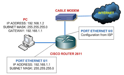
As I said in the last post, the interface ethernet 0/0 is connected to the cable modem and interface ethernet 0/1 connected to my PC like shown below:


Ethernet 0/0 is using configuration got from the ISP so we'll set it to receive IP address from ISP's DHCP server. Always remember to give no shutdown command on the interface:

router> enable
router# configure terminal
router (config) # interface ethernet 0/0
router (config-if)# ip address dhcp
router (config-if)# no shutdown

Now to set the Ethernet 0/1 port as the picture above, we can just jump right to the interface 0/1 configuration mode:

router (config-if)# interface ethernet 0/1
router (config-if)# ip address 192.168.1.1 255.255.255.0
router (config-if)# no shutdown

You have successfully configure IP addresses to your interfaces, you can check it using the following command:

router# show ip interface brief


InterfaceIP-AddressOK?MethodStatusProtocol
Ethernet0xxx.xxx.xxx.xxxYESDHCPupup
Ethernet1192.168.1.1YESNVRAMupup


The show ip interface brief is a very useful command, you would want to use it to check the status of your interfaces.

The interface column shows you all the interfaces you have, the IP-Address is of course shows the addresses of the respective interfaces.

The Method column shows whether the addresses given by a DHCP server or you configured it yourself (stored in NVRAM) or it can also shows TFTP - configuration from TFTP server.

When the status column is showing down then it indicates there is a problem with OSI Layer 2.
The protocol will show up if the interfaces are physically connected to other devices, if not they will show as down (a problem with the OSI Layer 1).
And there's also another state of the status column -administratively down - it means the interface is shutdown.
This is the most likely question you'd get in the CCNA exam.

You can read further about show ip interface brief command here.

When you finished this configuration, your router will be receiving IP address on interface 0/0 from DHCP server of the ISP, and the interface 0/1 will be ready to communicate with network 192.168.1.0

Please read also:
Configure Cisco Router to Work With Cable Internet - Part 1
Configure Cisco Router to Work With Cable Internet - Part 3
Configure Cisco Router to Work With Cable Internet - Part 4

Read more!

16 October 2008

Configure Cisco Router to Work With Cable Internet - Part 1


If you just bought your first used Cisco router, I bet one thing you want to immediately do is connecting the Cisco router to the cable internet.
I know I did, I have cable internet for my home network. Previously I used Linksys router to get my LAN connected to the internet.

Configuring Cisco router to connect to the cable internet is easy work, even if you know only the basic configuration stuff in Cisco.

I need to warn you that this configuration will be in series or else this configuration will be a very long post. And also this series will be a good chance to learn some aspects in configuring Cisco router.

All you need to do is to set the IP address of the interfaces, set the router as a DHCP server if you want it, configure NAT, and the last thing is routing. Very simple indeed.

I'm only going to show you to get your router up and running, I wont discuss about access list and other fancy stuff - that's for the next posts.
Also the devices involve in this tutorial is only the Cisco 2611 router, Motorola cable modem, and my PC. If you want to use other Cisco devices you might need to do more configuration.

In this Part 1, I'm going to review about the concept of this configuration, please look at the topology image below:

Configure IP Address of the Router's Interfaces

The router will get the ip configuration from DHCP server of the ISP, the Ethernet 0/0 port I use as the exit point to the internet.
The Ethernet 0/1 will be the port where my computer is connected. I'm going to set private IP address as the gateway for the computer.

Setting IP address of the interfaces is definitely a topic in the CCNA exam.

Configure the Router as DHCP Server

In this example I'm using the router as DHCP server, giving IP addresses to the computer along with other configuration such as subnet mask, gateway address, and the dns server ip address.

You won't be tested about setting router as DHCP Server in the CCNA exam, it will show up in the CCNP exam.

Configure NAT (Network Address Translation) in The Router

NAT is a powerful concept, you have one public IP address given by the ISP and also private IP addresses in your LAN.

What NAT will do is translate all your private IP address into the public IP address. If you're using overload - one public IP address used by many private IP address - the private IP address is converted into logical ports.

For example, if you got public IP address of 10.1.1.1, then the form of the translation might be like this 10.1.1.1:3000

NAT is also a topic in the CCNA exam and one of the thoughest that is.

Configure Routing

This example only shows the basic static routing, the router will send all request from the client (from port Ethernet 0/1) to the port Ethernet 0/0.

You surely want to learn about routing for the CCNA exam.

Please read also:
Configure Cisco Router to Work With Cable Internet - Part 2
Configure Cisco Router to Work With Cable Internet - Part 3

Configure Cisco Router to Work With Cable Internet - Part 4
Read more!

08 October 2008

Fastest Way to Recover or Upgrade Cisco IOS using tftpdnld


There are many articles about how to recover or upgrade your Cisco IOS, but personally I find that using tftpdnld is the fastest and easiest way to do this.

tftpdnld is a command that you can use in the ROMmon mode of Cisco devices.

Using tftpdnld you can download files directly to the Cisco routers or switches from ROMmon mode using the console cable (serial connection).

In order to use the tftpdnld command you need a TFTP server running in your computer, any TFTP server will do.
In this example I recover my Cisco IOS image for my 2611 router, but this tutorial also good for 2800 and 3800 series routers.

I need to tell you that you can use tftpdnld to download image file from TFTP server to the router but not from the router to TFTP server.

Also this command requires you to use the first LAN port in the router - in 2611 is ethernet 0/0 port like shown below.


But in 2621 router you can also use the Token Ring or Fast Ethernet port.


WARNING!!!
Use this tutorial only if you understand the effect of the commands provided and you aware the effect of the procedures shown to a production or running network!


First thing you need to do to recover or upgrade Cisco IOS is prepare your IOS image file in the TFTP server folder.

Next is to get in to the ROMmon mode of the router.

In the ROMmon prompt, you need to set up some configuration for router to TFTP server connection. In this example I use the following configuration:


Issue the "set" command in the prompt, it shows the current configuration you've made, next is to type in the following commands:

rommon 1 > set

rommon 2 > IP_ADDRESS=171.68.171.0
rommon 3 > IP_SUBNET_MASK=255.255.254.0
rommon 4 > DEFAULT_GATEWAY=171.68.170.3
rommon 5 > TFTP_SERVER=171.69.1.129
rommon 6 > TFTP_FILE=c2600-is-mz.121-2.T.bin

Make sure you got everything right and your TFTP server is connected to the first LAN Port of the router.

Before issuing the tftpdnld, Cisco docummentation tells that in 2600 and 1720 series router, the tftpdnld in ROMmon mode might report a bad checksum comparison when it loads Cisco IOS software images of Cisco IOS Software Release 12.0(2.2)T or later - it's a bug thing.

To overcome this problem you need to issue another command:

rommon 7 > TFTP_CHECKSUM=0

Next you're ready to isssue tftpdnld command, type in the command as shown below then it will show you some output, answer y to the question prompted to you.
The question shows you that the content of the flash memory will be erased and replaced by the downloaded image file.

rommon 8 > tftpdnld

IP_ADDRESS: 10.1.1.1
IP_SUBNET_MASK: 255.255.255.0
DEFAULT_GATEWAY: 10.1.1.1
TFTP_SERVER: 10.1.1.2
TFTP_FILE: c2600-is-mz.121-2.T.bin

Invoke this command for disaster recovery only.
WARNING: all existing data in all partitions on flash will be lost!
Do you wish to continue? y/n: [n]: y

Receiving c2600-is-mz.121-2.T.bin from 10.1.1.2 !!!!!.!!!!!!!!!!!!!!!!!!!.!!
File reception completed.
Copying file c2600-is-mz.121-2.T.bin to flash.
Erasing flash at 0x607c0000
program flash location 0x60440000

rommon 9 >

At this point your new image will be in the flash memory if there is no problem with the connection from TFTP server to the router.

You can verify that your image exist in the flash using the following command:

rommon 9 > dir flash:
File size Checksum File name
4603828 bytes (0x463fb4) 0x9719 c2600-i-mz.121-2.T.bin
rommon 10 >

Last thing to do is to set the boot command to tell the router that you want it to boot using the image file you just downloaded:

rommon 10 > boot flash:c2600-i-mz.121-2.T.bin
program load complete, entry point: 0x80008000, size: 0x51c0dc
Self decompressing the image : #################################################
##################################
...

That's it you just successfully recover your Cisco IOS image, check the new image using the show version from the router prompt:

Router2611>sh version
Cisco Internetwork Operating System Software
IOS (tm) C2600 Software (C2600-I-M), Version 12.1(2)T, RELEASE SOFTWARE (fc1)
Copyright (c) 1986-2000 by cisco Systems, Inc.
Compiled Tue 16-May-00 15:15 by ccai
Image text-base: 0x80008088, data-base: 0x80865F64

ROM: System Bootstrap, Version 11.3(2)XA4, RELEASE SOFTWARE (fc1)

Router2611 uptime is 1 minute
System returned to ROM by reload
System image file is "flash:c2600-i-mz.121-2.T.bin"

cisco 2611 (MPC860) processor (revision 0x202) with 22528K/2048K bytes of memory.
Processor board ID JAB0317052N (1135645455)
M860 processor: part number 0, mask 49
Bridging software.
X.25 software, Version 3.0.0.
2 Ethernet/IEEE 802.3 interface(s)
1 Serial network interface(s)
32K bytes of non-volatile configuration memory.
8192K bytes of processor board System flash (Read/Write)

Configuration register is 0x2102


Read more!

25 September 2008

Using Putty for Connecting to Cisco Devices [VIDEO POST]


This should be my first time posting a video post, as much as I'm so nervous when recording it, I also enjoying it actually.

I decided to make video posts since you can learn how to configure networking devices much easier with videos.

Sure, connecting to Cisco devices using Putty is easy, anyone can do that, I know, but since this is my first time recording myself, it's still rough so you have to excuse me okay sengihnampakgigi
Also pardon for the bad English since it's not my mother tongue.

This post also related to my previous post about Serial to USB cable converter, be sure you check that post also.


All comments about this post are very much appreciated, I'd do better next time, thank you for watching.
Read more!

23 September 2008

But, My Laptop Has No Serial Port???


I reviewed about using console cable for connecting to your Cisco devices at my previous post, we know if we want to configure our Cisco devices for the first time we're going to need console cables.

Console cables have RJ45 connector at one end and Serial connector at the other end, the problem with this is that most of the newer laptops produced nowadays don't have any serial port.

Sure the laptops got smaller and lighter, but no serial port? This can be a slight problem for us, network engineers.

There's a way to get around this, we can use Serial to USB Converter cable. What this cable does is it converts your console cable serial connector so you can plug it to your USB port.

You can see at the image on the left is an example of Serial to USB converter cable, you can find many vendors produce this kind of cable.

To use it for your laptop is an easy work, all you have to do is install the driver, some cables can just work when plugged in, and sometimes you have to find the driver update first so it can work with your OS.

This happened to me once, I got my converter ready, did the correct parameters for connection but I can't connect to the router.
I search every possible cause for hours only to find that my converter driver need to be updated. So words of note, don't forget to download your driver update.sengihnampakgigi

When you done with the driver installation, the installation window will tell you where is the converter located COM1, COM2, or other.
If not, you can look at your Windows Device Manager and point to the Ports (COM & LPT), there you can find the location of your converter.


I'm not sure if this is true, but whenever you move your usb converter to other usb port, it will change the COM port number.
Just to be safe, remember where you plugged the converter for the first time and always plug there.

Next, you can use the converter to connect to the routers/switches. I used HyperTerminal Private Edition for this example:


Give a name for the connection then choose the COM port of your converter from the Connect using drop down menu.
Make sure you have the following parameters set:

  • Bits per second : 9600
  • Data bits : 8
  • Parity : None
  • Stop bits : 1
  • Flow control : None


Click OK and you're ready to go.


Read more!

01 September 2008

How To Terminate UTP Cable to Toolless Modular Jack


Last post I talked about how to terminate to Modular Jack, it was not hard at all right? There are also modular jacks type that are toolless.
The toolless jacks allow you to terminate UTP cable without the punch down impact tool, though you still have to use cable stripper and scissor, so they're not exactly toolless.

The one that I once tried using before was the one from AMP, lets see if they really cut down the time in terminating the cables.


The tools you need is exactly the same when terminating to regular jacks, but you can exclude the punch down impact tool and add a cutting tools like scissor or cutter.
Here are the steps:

Step One:

Still same with the regular jacks, strip the cable jacket and untwist the cables.

Step Two:

Insert the cables to the holes according to the color codes printed on the jack

 
Now this process takes a little bit more time if this is your first time terminating cables to toolless jacks.
Step Three:
Cut the excess cables using scissor or cutter, it would be easier to use technician scissor.

Make sure you cut them in even length.

Step Four:

Close the cover using your hand, this is quite hard, just close it until you're sure it's firmly closed, and attach the jack to the wall face plate.

 
There you have it, toolless modular jack termination.
In my opinion, I prefer to use the regular jack instead of the toolless ones, I'm more used to terminate to the regular ones and for me, it's harder to arrange the cables in the toolless jacks.
Then again it's up to you to choose, in term of price, the regular and the toolless jacks are not too much different, but the punch down impact tools do cost some good amount of money.

Read more!

29 August 2008

How To Terminate UTP cable to Modular Jack


It's easy to do your own home networking, if you want to run your cables in your walls you're going to need the tools shown in the left picture.

Of course for the cable you need to run it down first in your walls, I only use that short cable for this tutorial.

Words of note, do not cut your cables too short when terminating them to the modular jacks. In case you need to change the jacks later or you terminate them wrong then you don't have to worry having too short cables.

Step One:

Strip your cable jacket using the cable stripper.


Step Two:

Prepare your modular jack, you can see the jack has printed color codes for terminating the UTP cable. It is really up to you which color codes you choose for terminating the cables, the important thing is to keep it uniform in your project.


Personally I like to use the T568B color codes for my projects.

Step Three:

Position your cable and the jack like the following position, and arrange the cables according to the color codes you'd like to use.


Step Four:
Now it's time to use the Punch Down Impact Tool, if you look closely at the tool, you'd see different tips at it, you have to remember to position the sharp tip on the outer side of the jack.

This tool has two functions, first it push the cables in to the slots on the jack, and the sharp tip is used to cut the excess cables.

As its name, the tool would have an impact when used, so you might want to put the jack on the floor and put something beneath it like carton or anything else to reduce the impact of the tool.


In a project where you have to terminate many jacks, it would just hurt your hand or back to terminate these things, you can use tools such as this EZ Grip Puck.


On the left is the result when you finish using the punch down impact tool.

Note:
This is not recommended but if you don't have impact tools, you can use anything that has slim shape to insert cables into the slots of the jack and then you can use scissors or cutters to cut the excess cables.

Step Five: 

Prepare your wallplate, you can see on the backside of it, it has a place where you can plug your jack.


Insert your jack at the area shown in the picture above, be careful if you put the jack wrong, you cant insert the cable for your computers in it. Make sure you position the jack as the following pictures:
 

Happy trying.

Read more!